Velocity Vector Diagram Centrifugal Pump Centrifugal Pump (d
Velocity diagram of centrifugal compressor Velocity centrifugal diagram compressor fluid following Centrifugal compressor velocity increases radial traingle
Analyzing a Centrifugal Pump Design with Frozen Rotor Approximation
Velocity centrifugal diagram compressor inlet triangle blade angle outlet enters hence axially air Pump centrifugal parts engineering marine mechanical construction pumps explained techno graphic important science motor board ships 3d plomeria chemical electrical Centrifugal volute casing increase impeller diffuser fluid sectional principle
1. main components of a centrifugal pump (taken from [47])
Velocity diagram of centrifugal compressorWork done by the centrifugal pump on water Velocity pump centrifugal triangleHow to make a simple centrifugal fan.
Velocity triangle for centrifugal fan and blowerHow to draw velocity triangles for turbines at how to draw Centrifugal pump (drawing)What is a centrifugal pump? understanding its mechanism, types, and.

Centrifugal pump: principle, parts, working, types, advantages
Centrifugal velocity triangle fan impeller blower inlet outlet blades types differentVelocity triangle or diagram of centrifugal pump 5 . 2 vector diagramVelocity diagram of centrifugal compressor.
Lecture 5.8 total head of centrifugal pumpIntroduction to centrifugal pumps pdf Centrifugal pump diagramThe velocity triangles at the runner of a pump-turbine in turbine mode.

Velocity triangle of centrifugal pump || centrifugal pump
Velocity impeller diagram work doneWhat is a centrifugal pump ? Velocity triangles diagram for impeller of centrifugal pumpPump centrifugal velocity pressure rotor frozen approximation analyzing comsol magnitude distributions.
Teaching and learning resourcesHow pressure increases in centrifugal compressor? Analyzing a centrifugal pump design with frozen rotor approximationPump centrifugal basic pumps circulating works principle operation water volute flow quora inside priming troubleshooting impeller types motor casing maintenance.

How a centrifugal pump works
Velocity vectors for the centrifugal pump model at 3,500 rpm and 3Centrifugal velocity triangles inlet impeller Velocity triangle or diagram of centrifugal pumpCentrifugal pump velocity triangle lecture.
Analysis and simulation of the 3d created centrifugal pump and obtainCentrifugal pump Velocity diagram centrifugal compressorPump centrifugal working parts principle types advantages application main its disadvantages components suction valve impeller foot delivery pressure strainer pipe.
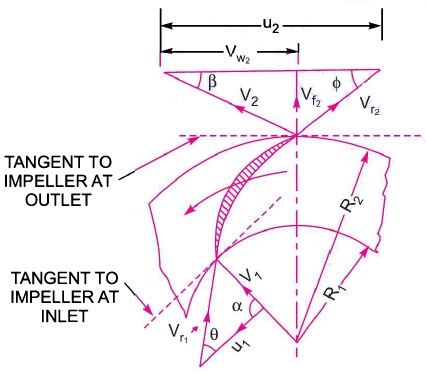
Velocity pump centrifugal triangle
Velocity diagram of centrifugal compressorVelocity diagram and work done by impeller Velocity triangle diagram and work done of centrifugal pump ~ heads andTechno-graphic: important parts of centrifugal pump on ships explained.
Centrifugal definition principle mechanical turbine obtain mass created linquipVelocity pump centrifugal triangle diagram | velocity vectors for the centrifugal pump model at 3,500 rpm and 31) centrifugal pump construction.


Velocity Diagram And Work Done By Impeller - YouTube
![1. Main components of a centrifugal pump (Taken from [47]) | Download](https://i2.wp.com/www.researchgate.net/profile/J-Statharas/publication/336242931/figure/fig1/AS:810038130139136@1570139548687/Main-components-of-a-centrifugal-pump-Taken-from-47.png)
1. Main components of a centrifugal pump (Taken from [47]) | Download

Analyzing a Centrifugal Pump Design with Frozen Rotor Approximation

How a centrifugal pump works - ViduWeb

Velocity Diagram of centrifugal Compressor - YouTube

Velocity Triangle Diagram And Work Done Of Centrifugal Pump ~ Heads And

What Is a Centrifugal Pump ? - Find Pump Suppliers In Malaysia | Pump